Hi!
First of all, this is still very basic. I just managed to get my first results running, but I figured I would share my thought process & what I have done so far.
I'm not that well versed when it comes to Math, so I'm definitely looking forward to hear your guys opinions.
This thread is quite long, so feel free to just jump to the heading that interests you.
Recently, @Boris The Brave has released a really nice tutorial on Marching Cubes & Dual Contouring. A few years ago, I was already messing around with those algorithms but was lagging the required knowledge about programming back then. When Boris' tutorial came up, it again arouse my interest in this type of field.
Also, let me appologize for my poor paint skills in advance ![]()
Classic Dual Contouring
The heart of the dual contouring algorithm is to solve the problem of finding the best fitting vertex for a surface inside of a cell. In the original paper, this problem has been solved with a quite complex solution (at least to us non-mathematicians): Solving & minimizing the Quadratic Error Funtion (QEF)
Most projects simply reuse the original paper's implementation to solve the QEF and/or (slightly) adjust it to their needs. Usually, this works perfectly fine & yields pretty good results.
However, I was curious if I could find a way to simplify the problem.
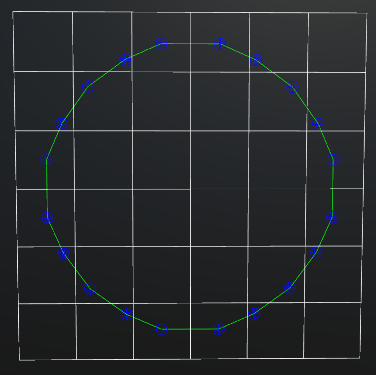
My approach (2D)
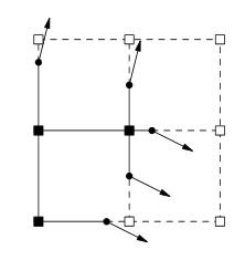
- We know the exact position of a sign change on one or more edges.
- We know the normal of the surface at that exact position
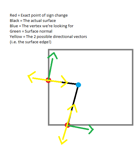
Since we know, that we have 2 or more sign changes in this cell, we know that there is either going to be an intersection of those 2 lines inside of the cell, or none at all.
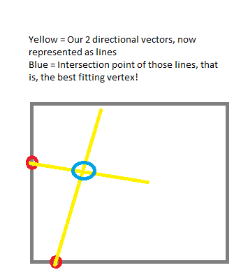
So, here's all we need to do summarized:
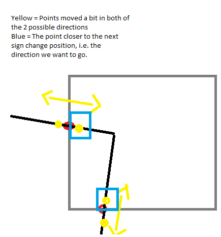
- For each sign change, calculate the 2 orthogonals to the normal
- For each other sign change, do the same
- Look for an intersection between those 2 resulting lines (Essentially, we are looping over all sign changes twice.)
In the end, we simply take the median of all found intersection points (required if there are more then just 2 sign changes)
My approach (3D)
In 2D, we can represent the course of a surface in a specific point with the tangent line.
In 3D, the same principal exists. This time, it is a tangent plane.
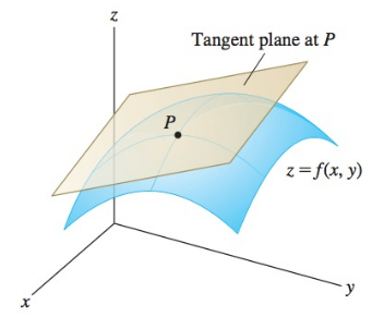
We can apply the same principal as in 2D to find the one vector we are looking for, to represent our surface edge at this point.
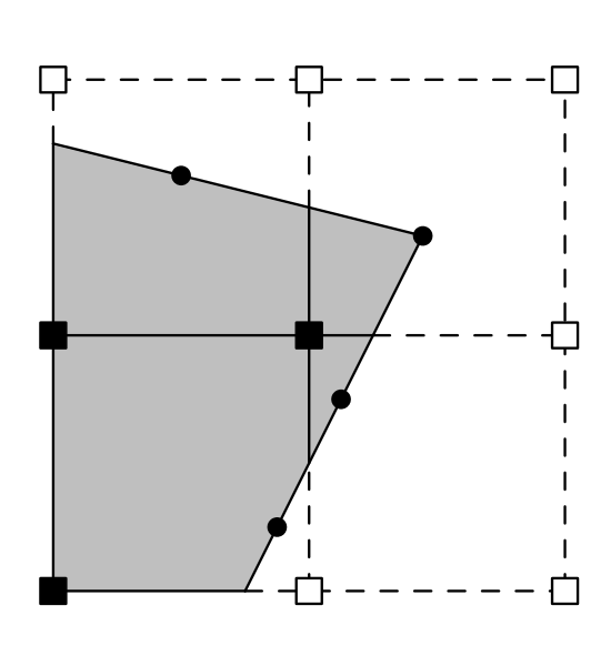
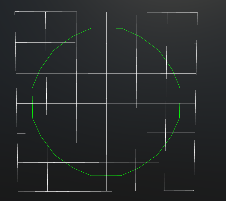
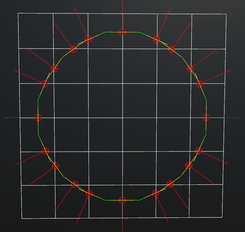
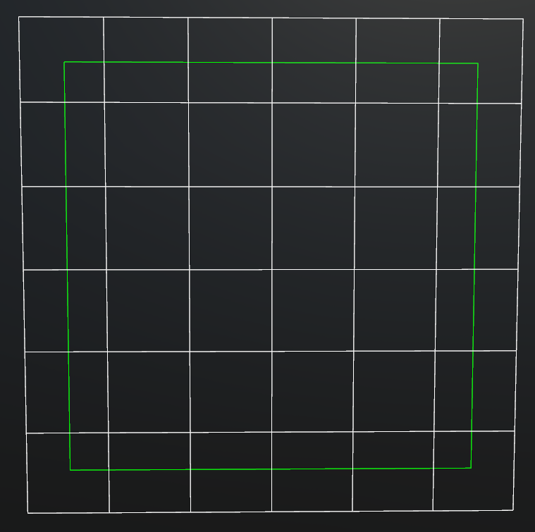
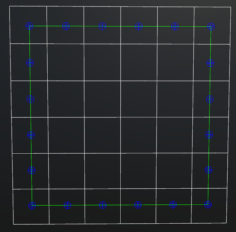
Results in 2D
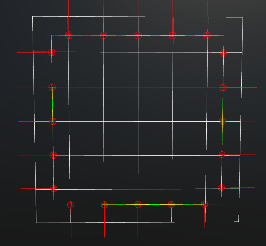
Results in 3D
Left: My approach, right: The result from Boris The Brave's implementation.
https://youtu.be/LtZCa359exU